
This section describes a few of the past projects I've worked on. I have tried to provide sufficient detail about the projects to be interesting and informative, while also being sensitive to the companies' proprietary value and of course not to violate security constraints. Much of the higher level content of these pages can also be found in other publicly accessible web sites, some of which are linked to here. I do not make any claims concerning the accuracy of other sites and cannot be held accountable for any of the content they may contain. A brief introduction to these projects follows. To read more about them, click on the buttons to the left. The links in the introductory paragraphs below provide overview information from the web.
I'm proud of the involvement I've had in these projects, both in the capacity of meeting technical challenges and finding effective solutions, and in the leadership capacity of moving the project goals forward. Personal satisfaction is an important part of the work experience, and that's a common thread that runs through these projects for me. I hope you enjoy reading about them as much as I've enjoyed working on them.
At Grumman (now Northrop Grumman) I worked on the EA-6B Prowler, a unique radar jamming aircraft. I developed the operating system software, and created the program loading and data recording subsystems, in addition to other functions. This was one of the most technically challenging and rewarding positions I've ever had. Grumman had the single best group of people I've ever been honored to work with. Read more.
At Baxter Healthcare I worked on all software aspects of the Amicus aphaeresis blood collection system, and on a photoreactive pathogen inactivation device for platelets and plasma. Both devices are important to maintaining the health of individuals and the general public, whose full potential may not be realized for some time yet to come. Read more.
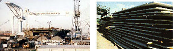
At Newport News Shipbuilding (now also a division of Northrop Grumman, but at that time a division of Tenneco), where nuclear powered aircraft carries and attack submarines are built, I did the analysis for a major revision of operations for the plate handling yard. Although this began as a software proposal, it became a complete manufacturing process proposal, supported by a central software package design. Read more on this project. I also completed the development of a PC based controller for an automated pipe cutting robotic project. This was the first use of a PC on the shop floor at the shipyard, and their first system that went directly from design data to a finished manufactured part without human intervention. Read more.
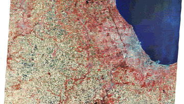
As a contractor to NASA, I spent a year on their Landsat 2 program, improving the image analysis and classification software in this Remote Sensing Earth Resources Satellite project. Currently the Landsat 7 project is run by the USGS.
Before that, I got my start building operating systems and telecommunications for the New York banking industry. This was when remote teller stations and ATMs were just getting started.
| Landsat Earth Monitoring Satellite | Steel Plate Handling | Pipe Cutting Robot | Amicus Blood Donation Device |
NASA - Landsat Earth Resources Monitoring Satellite |
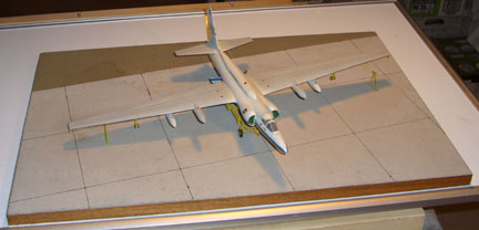
I'd always wanted to work for NASA. I was interested in science from my earliest days. The science books by Isaac Asimov fired my imagination more than his fiction did, and I read as many of his books as I could find. It was Lester del Ray's classic "Rockets Through Space" that first fired my imagination about space travel. I was even a member of the Planetary Society and the L5 Society. One year I audited an astronomy course at Columbia University, and I discovered NASA had a branch office associated with the college, he Goddard Institute for Space Studies, where Robert Jastrow was the director. I applied for a job and received an offer as a scientific programmer, doing data analysis for the Landsat 2 satellite. The satellite flew in a medium altitude polar orbit (920 km or 570 miles), maintaining a sun synchronous attitude with the surface of the Earth, flying overhead at roughly 9:30 am local time. The means the illumination angle in latitude was always the same. The satellite has a telescopic camera that scanned the Earth as it flew overhead, sweeping the view in latitude as the craft traveled in longitude. Notice how the picture provided above is slanted. This is mostly due to the orbital inclination of 81 degrees, but effects from the rotation of the Earth underneath the satellite during the flight time of the picture had to be accounted for as well. The telescope's beam was split into four parts which went through individual narrow band pass filters, providing four spectral data points for the same location simultaneously. Two of these values determined the infrared intensity (both near infrared), one was in the visible red region and the forth was in the visible green region. The spatial resolution of each pixel was about 80 m (250 ft) when contrast was normal, which is fine for agricultural and geologic use but is inadequate to be of use for military intelligence (high contrast linear features, like a paved road through a corn field, could usually be seen down to 10 m or 33 ft). The collected data was transmitted to Earth in real time if within range of a ground station, or recorded in the satellite for later transmission to a US receiving station. Receiving stations were also built in several other countries around the world, such as Brazil, Canada, Iran, Italy and Zaire,. Once received, the data was stored on magnetic tape reels, and these tapes were then sent to us, where the data was input to Fortran programs for analysis. The analysis was used to identify the material seen by the satellite, and different materials could be assigned arbitrary colors in the final image. This is how maps like the one shown above were made. The technical details of the categorization algorithms were based on the relative intensities between the spectral values for each pixel intensity in a six dimensional phase space. First, we calibrated the data given the known response of the optical sensors. Then we normalized the readings of all the intensities so that differences in brightness across the image would not skew references to past history. Brightness was defined as the square root of the sum of the squares of each color. The dimmest pixel's value was subtracted from all the other pixel's, producing a zero point. The brightest pixel's magnitude then divided all the other data points, producing a maximum magnitude of 1. Thus modified, the six ratios between the four readings for each point were calculated. To be explicit about that, let's call the four spectral reading for each point w, x, y, and z, going from longest wavelength to shortest. The first dimension in phase space is the ratio w/x, the second is w/y, and the third w/z. The fourth and fifth are x/y and x/z respectively. Finally, the sixth dimension is y/z. Pixels which give rise to phase values that cluster near other phase values are grouped together and identified as probably the same substance. Let's explain that by a physical example. Vegetation is typically very reflective in the green region and dim in the visible red, but bright in both infrared bands. Dry soil is brighter in the visible red then in the green, and only moderate in the infrared. Wet soil is somewhat dimmer in the visible bands, and somewhat more dimmer in the infrared. Bodies of water thicker than a few centimeters are dark in all bands. In this way the various types of substances seen can be identified, and to an extent even the conditions that affect them. For example, dehydrated corn is dimmer in both infrared bands then healthy corn, but insect damaged corn may be dimmer in only one infrared band. Unfortunately, given the limitations of the earlier versions of these satellites, by the time insect damage could be detected from the satellite and the data processed, the crops were already very badly damaged. Libraries existed of known values in phase space for most of the possible results. This was done by the collection of "ground truth" in correlation with what the satellite saw. During the early stages of the project's development (before my time there), after an image was processed that yielded unknowns in phase space, data would be collected locally. This was done in various forms, from high flying U2 aircraft carrying high resolution cameras and equipment similar to what the satellite used, to low flying planes with movie cameras to graduate students in jeeps with notebooks and pencils. The libraries of phase space values were then updated accordingly. A few years later, to commemorate my involvement with this project, I built a 1/48th scale model of a U2, specially painted in NASA colors and marked as Earth Resource Aircraft No. 4. A brass plaque labels the diorama simply as "The Truth." Just as an aside, here's a photo of my model: However, we used other information to improve the accuracy of our analysis, and continually research new methods. The results of the phase space calculations were combined with masks of the location data. That is, pixels located close together both in phase space and geographically were assigned a higher confidence of being the same substance as pixels nearby in phase space but far apart in real space. In effect, we could use this data to redefine what was meant by "nearby" in phase space dynamically. For example, a field of wheat one one side of the image and a field of straw on the other might be sufficiently close in phase space to be identified as the same substance, but if forced to be identified by the geographic constraint might be recognized for what they individually were. Or, a cluster of a dozen pixels might be identified as sagebrush but a cluster of several hundred pixels might be identified as prairie. If the dozen pixels were between the prairie pixels and an area confidently identified as concrete, it could be identified not as sagebrush but as a mixed border of prairie and concrete, possibly at an airport. Other areas involved looking at regions of phase space by the center of gravity method, seeing how the distribution of pixels changed as a function of directional differentials. Or were identifications better when the distribution was assumed to be flat? How does the shape of the clusters in phase space affect classifications (for example, urban rooftops show much greater variation in the infrared than they do in the visible)? Does making several passes through the data using restricted dimensional information yield the same results as processing all the dimensions in one pass? Does processing four quadrants of the image separately give the same results as processing them all together? What information can be gleaned by the differences? Such questions made for ongoing experiments. The following links allow interested persons can learn more about the art and science of remote sensing and the current Landsat program in general. |
Newport News Shipbuilding Plate Handling SystemThe Plate Handling System began as a study to see how computers could be used to improve the handling of steel plate at the shipyard. During this period, under mandate from the Navy, the company was exploring innovative avenues of improving their manufacturing processes. A team of people from various departments was assembled, with myself representing the Computer Aided Design and Manufacturing department. Previously computers were used primarily as a drawing tool, but the time was right to exploit their potential further. With such vague requirements, we set off to make a thorough understanding of how steel plate was used in the shipyard. In the first three months we interviewed people at all levels in the plate handling yard, from senior management to inventory clerks to crane operators and fabricators. Surprisingly, the shipyard was quite unique in their methods of handling plate. For one thing, the sizes of the plates was unusual. Intended for use on aircraft carriers and submarines, the plates could be up to twenty-five feet by fifty feet, with thicknesses sometimes exceeding four inches. That makes for a very heavy plate! There was also a wide variety of types of steel, aluminum and other materials. Steel was by far the most common material used in the domain of this study, both in it's quantity and because aluminum couldn't be handled by the magnetic cranes. Because of chemical interactions, some plates cannot be allowed to come into contact with other plates. The shipyard is also unlike most other business in that they do not actually own the plate in their inventory; the Navy does. The Navy is given a list of plate necessary for the construction of a specific phase of a certain vessel, and they buy the steel and provide it to the shipyard. This detail, the contract number of the buy and the ship the plate was intended for, becomes a portion of the part number assigned to the plate. Further, traceability requirements on each plate is extreme. Ever since the loss of the submarine Thresher, each plate is identified by lot from the foundry pour, and follows downstream to each part made from that plate. The identification flows upstream as well, so that if a part ever fails on any ship, the Navy can identify the steel plate it came from, and all other steel plates made in that pour, and all the parts made from all those plates. In this way inspections and repairs can be made proactively on any ships that may be at risk. The plate yard consisted of several workshops where plates were cut to size and shape, tagged appropriately, and sent off to other departments for further manufacture. Surrounding these workshops were the stacks, where dozens or hundreds of plates would lie on top of each other, perhaps to twenty feet high. Cranes, either tracked or on gantry rails, would straddle the stacks to acquire a targeted plate and deliver it to the staging area. The weight of these stacks is so great that occasionally plates would be "lost," driven into the summer softened asphalt by their overburden and then held too tightly for the crane to lift. The way the yard normally operated was as follows: a work order would be received calling for a particular plate by it's part number would be received by the plate handling yard. the database of plate would be referenced. The stack it was stored in would be identified, as well as it's position within the stack. At the time, this database was a series of small boxes holding index cards, on which were written the data about the plate they represented, one card per plate. A retrieval order would be generated that scheduled a particular crane to acquire the plate, and said where to deliver it to. When the time came, the crane operator would go to that stack, lift the first plate, and see if it was the plate targeted. If not, he would deposit that plate on a staging area and go back to the stack for another plate. If that was not the designated plate, it would also be deposited on the staging platform on top of the other plate. This would continue, the operator "tearing down" the stack, until the exact designated plate was acquired. This would be dropped off at the destination area, and the operator would then go back to the staging area, acquire the top plate from that stack, and put it back on it's home stack. This would be repeated until all plates from the staging stack was restored to it's home stack, in an operation known as "rebuilding." This is how the inventory was maintained. Clearly, that involves a lot of plate movement, especially unnecessary when an identical plate was available closer to the top of the stack, even if it wasn't the exact one purchased for that contracted vessel. We proposed keeping the database on computer, associated with the contracts database. This computerized database could be searched to find the exact specified plate, as well as a plate which was physically identical to the desired plate that was closest to the top of any stack. If two stacks had suitable plates equally close to the top, the stack closest to the delivery area would be selected. The computer could then exchange these plates (the audit trail required "buying" the highest plate from whatever contract owned it and "selling" the original plate to that other contract--a trivial activity for the computer). The crane would then be scheduled, and only a much smaller amount of the stack would have to be torn down and rebuilt. We estimated that this change alone could save the plate yard almost 40% of their budget. In addition, we proposed using bar code scanners to identify the plate. We suggested two types of labeling for the scan codes; one using Mylar adhesive labels on the side of the plates, and the other painted large on the top sides of the plate, using a type of reflective paint similar to the way white lines down the highway are painted. We identified a turnkey camera system (hardware and software) that could read those bar codes from the crane operator's cabin from twenty feet above the plate, even in the moderate fog that was not uncommon in Southeastern Virginia. We expected this top barcode to have a lifespan of eight weeks before abrasion from overlying plates made it unreadable (longer if plate teardowns were reduced as we proposed), and at that point it could be repainted from the side label. We also examined the use of computer software to calculate the nesting loft for each plate. This means that when several smaller shapes have to be cut from a single plate, what is the optimum placement so that as much plate is left over as possible. This is actually an NP-hard problem, one for which there is no theoretically best algorithm. However, which a best solution cannot be proven, pretty good solutions aren't hard to come up with, especially for a person with experience. We surveyed the state of the art in nesting software, and were disappointed compared with the results claimed by the plate yard for their people. We recommended that this task continued to be done manually, with another survey done in five years. Similar results were obtained for the storage of leftover plate, which could be of irregular size and shape. At this point, we presented our findings to management. When I left the shipyard a year later, after completing the Pipe Cutting Robot project, the status of this proposal was still undecided. I believe the main problem here was that union rules did not allow any workers to be eliminated or displaced due to automation. Since plate handling was not a bottleneck to production, and since the Shipyard did not invest in it's inventory, immediate changes could not be justified. This was also a problem on the Pipe Cutting Robot project, but since that area required much higher numbers of laborers, normal attrition allowed more room to bring in advanced equipment without violating the union contract |
Where is the Prowler?
 Amicus
The Amicus is an aphaeresis blood donation separator. This means that during the donation, a single component is separated from the blood, and the remaining blood is returned to the donor. Typically the device is used to collect single donor platelets, though several other protocols (an organized collection of procedures) targeting different products can be run. A specially designed kit is installed on the machine--this kit contains a bag of saline, a bag of citrate anticoagulant, collection bags, and optionally an additive solution for post collection sterilization processing. Another part of this kit is a thin rectangular collection chamber that is wrapped around a centrifuge bowl. The donor is attached to the device using a typical medium bore donation needle, and a relatively small amount of blood is drawn from the arm using a stepper motor driven peristalsis pump. An optical interface monitors the level of red cells and platelets as calibrated light from a set of LEDs light passes through the blood fluids and is reflected back to a sensor. Although the RPM of the centrifuge can be controlled by software, a more effective way to maintain the collection efficiency is to adjust the blood flow rate, thereby altering the pressure in the centrifuge to maintain the proper separation of blood components. The separated components are drawn off using other peristaltic pumps through separate outlet ports in the collection bag. Blood components not targeted for collection are returned to the donor via a second needle to the other arm.
The device can also operate in single needle mode, where an extra reservoir of blood is drawn from the donor to maintain continuity of processing through the centrifuge, while the routing of fluids through the kits can be dynamically controlled to allow changing the direction of flow to the donor, thus returning the residual processed blood through the same "stick" that the blood is drawn from. Though the procedure takes a bit longer in this mode, many donors find it more comfortable. In either single or double needle mode, a unit of packed red cells can be collected at the same time at the discretion of the operator.
Another procedure the machine is capable of is the collection of mononuclear cells. These are essentially blood stem cells that maintain the continual supply of blood, sine blood cells have an average lifespan of only 20 days. Before chemotherapy treatments, the patient is given a drug which causes these cells to migrate out of the bone marrow. The Amicus device, running with a special kit and protocol, is then used to harvest these cells, which removes them from the donor for temporary storage so they are not affected by the chemotherapy. After the therapy has been administered, the mononuclear cells are transfused back into the donor. This method allows the patient to tolerate higher dosages of chemotherapy and shortens their recovery time, with substantial improvements to their quality of life during their illness.
This device, since it is directly connected to a human donor, is a class 3 medical device, and is subject to stringent FDA and CE Mark regulations. In addition to the documentation requirements, the entire team paid great attention to safety issues, and management supported all efforts in this area without compromise. The architecture of the device included an independent safety process, with redundant data lines to all sensors, and control of a relay in the power supply to cut power if the safety processor determined the device was not operating within expected limits. All valves and motors were spring loaded to fail in the position which isolated the donor from the device. This was critical to insure the donor was not injected with any air bubbles or unchecked quantities of anticoagulant, which could produce unpleasant to fatal effects. Naturally these possibilities were continually monitored during normal operation of the device as well. There was an ultrasonic sensor on the return line to the donor to detect the presence of bubbles at that point, which would trigger a reversal of flow to clear the bubble before resuming the procedure. Sensitive weight scales were built into the hooks holding the fluids bags, and the quantity of anticoagulant used was limited in short term time periods and throughout the overall donation. If either limit was reached, the procedure was immediately ended.
Software for this platform was written using a proprietary, in house developed language. It was a curious combination of a procedural language with lots of event driven statements. Structurally, the language operated in discrete work units, organized in a hierarchy of groups called modes, blocks and steps. From these, the compiler generated table entries which controlled the execution of generalized routines constantly running in the background. Each element had to be labeled, and each element had to contain a kind of GOTO statement that specified what section got control flow next under various conditions, such as normal termination, a specified condition being met, or an error event. One of my enhancements to this compiler was a scanner that assured each label was in fact used, to isolate "dead" code and to help find mistargeted labels. When you have to have so many labels, people tend to use similar names with numbers after them, which can be error prone. Control flow could also be changed by specifying a new mode. Some modes would be replaced by new modes, but some modes would nest inside others. Stand alone service functions could be written in C that operated either as on demand subroutine calls, or at periodic intervals, or in response to specific events. It was only how the functions were invoked that determined it's class, and the same function could serve in different classes at the same time (assuming they were properly coded to be reentrant). It was a difficult language to get used to, but once familiarity was attained, it performed well.
Two of my more significant contributions to this project were the PRP (Platelet Rich Plasma) Integrator effort, and the Excorporeal Blood Volume Estimator. The PRP Integrator was a substantial software effort requiring new coding and structural changes to existing protocols. This enhancement used an optical sensor to measure the turbidity caused by platelets in the output port line from the centrifuge. This was continually monitored, and the data integrated to estimate the procedure time required to maintain the programmed yield of platelets, which allowed us to adjust the quantity of plasma collected within that time, which is necessary to sustain the targeted quantity of platelets. Once the precise amount of plasma was collected the procedure could be ended. Since the Amicus device was not certified as a platelet counting device, no direct claims regarding collected yields could be made. However, the feedback provided by the integrator was shown in later clinical trials to produce platelet yields that were closer to the target and more consistently in less time than without the Integrator. The other task, the EBVE, was a planning tool that allowed the operator to input various parameters about the donor, such as their height, weight, age, and sex, in addition to the existing input data such as hematocrit, to more safely estimate donor total blood volume and limit the percentage of blood volume which could be withdrawn from the donor at any time. Both of these efforts were awarded patents to the teams that developed them, including myself.
Additional information on this device can be found at Baxter, Amicus Clearance, Amicus 501K, and Rapid Prototyping.